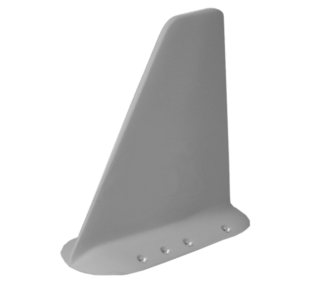
CNI22 Swept Blade Antenna

The true innovation, however, is the use of a one-piece metal casting for the base and antenna leading edge, which greatly increases side load strength, erosion resistance, and service life. Life cycle operating costs are reduced. Severe vibration and buffeting environments are accommodated by this design which is capable of high G resonance dwell. An additional benefit of the swept-back leading edge is radar signature reduction when compared to previous vertical blade antennas.

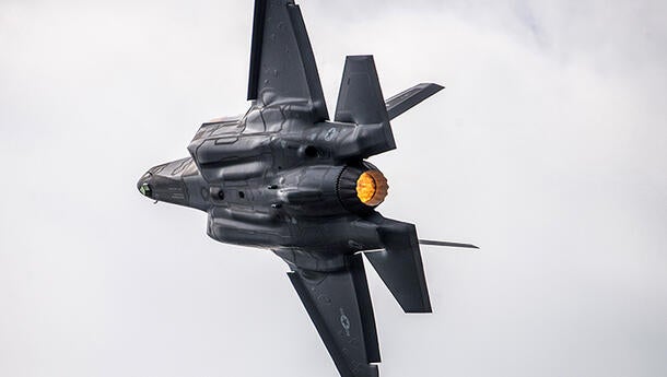
Several mounting footprint options are available for aircraft including the B-1B, F-15, F-16, and F-111.

Features:

  • Metal leading edge
  • Dual Frequency
  • Lo RCS
  • Erosion Resistant

CNI22 Antenna Specifications

Electrical
  CNI22-1 CNI22-4, -5 CNI22-9-1 CNI22-14-1 CNI22-15-1 CNI22-16
Frequency range (MHz) 225– 400
960 – 1220
225– 400
960 – 1220
225– 400
960 – 1220
225– 400
960 – 1220
225– 400
960 – 1220
225– 400
960 – 1220
VSWR 225–360 2.0:1
360–400 2.5:1
960–1220 2.0:1
1000–1100 1.8:1
225–400 2.25:1
960–1220 2.0:1
1000–1220 2.0:1
225–400 2.5:1
960–1220 2.0:1
1000–1100 1.8:1
225–400 2.5:1
960–1220 2.0:1
1000–1100 1.8:1
225–400 2.5:1
960–1220 2.0:1
1000–1100 1.8:1
225–400 2.5:1
960–1220 2.0:1
1000–1100 1.8:1
Impedance 50 ohms
Polarization Vertical
Isolation  
UHF to L-band >50 dB
L-band to UHF >50 dB
Radiation patterns Type of monopole
Power handling  
UHF 100 watts CW
L-band 2 watts avg
2.5 kW peak
2 watts avg
4.0 kW peak
2 watts avg
4.0 kW peak
2 watts avg
2.5 kW peak
2 watts avg
4.0 kW peak
2 watts avg
4.0 kW peak
Mechanical
  CNI22-1 CNI22-4, -5 CNI22-9-1 CNI22-14-1 CNI22-15-1 CNI22-16
Connectors
UHF TNC Female N Female TNC Female TNC Female TNC Female TNC Female
L-Band TNC Male N Male SC Female TNC Male N Female N Female
Weight 2.2 lbs max 2.5 lbs max 2.0 lbs max 1.75 lbs max 2.2 lbs max 2.2 lbs max

Contact the Antenna Team

Address

Related Domains & Industries

Solutions that solve our customers' toughest challenges.
view all capabilities