H Series Antenna Couplers

The couplers are designed to electronically split the received signals equally between the systems. In this manner, a single antenna may feed redundant systems or serve a dual-function role (e.g., glide slope and VHF Omnidirectional Radio Range Localizer [VOR/LOC]).

The ruggedly built couplers are housed in aluminum cases with all circuit elements fully encapsulated. General specifications applicable to all couplers are provided in this sheet, while Table 1 indicates the recommended function of the particular type.
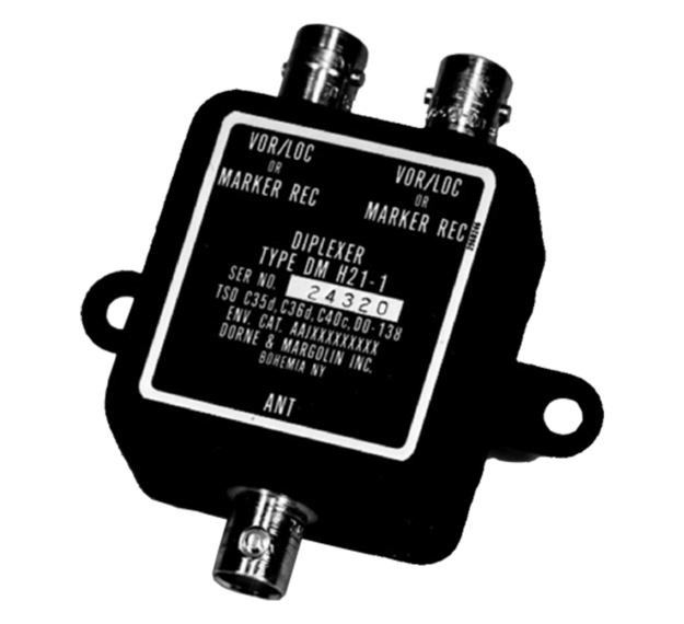
H Series Antenna Specifications

Download the H Series Spec Sheet
Electrical
Frequency range 329 – 335.3 MHz
108 – 118 MHz
74.75 – 75.25 MHz (H21-1 only)
VSWR
VOR/LOC < 1.5:1 dB
Glide slope < 1.5:1 dB
Marker beacon < 2.0:1 dB (H21-1 only)
Impedance 50 ohms
Isolation
VOR/LOC to VOR/LOC < 20 dB
VOR/LOC to VOR/LOC < 40 dB
Glide slope from VOR/LOC < 14 dB
Marker beacon to marker beacon < 14 dB
Insertion loss
Glide slope port H22-1 and H23-1 0.5 dB max
VOR/LOC port, H22-1 0.5 dB max
VOR/LOC ports, H21-1, H23-1 and glide slope ports H24-1 3.5 dB max including power split
Marker beacon ports, H21-1 3.6 dB max including power split
Power handling Receive only
Mechanical
Weight 4 oz max
Environmental
FAA TSO C34c, C35d, C36d, C40c

Contact the Antenna Team

Address

Related Domains & Industries

Solutions that solve our customers' toughest challenges.
view all capabilities